
中文 | English
Power-Pico
A Product-Grade Portable USB Ammeter and Low-Power Measurement Analyzer





📖 Project Introduction
Power-Pico is more than just a USB ammeter. It is a high-precision, low-power analysis tool designed specifically for embedded developers. To overcome the physical limitations of traditional ammeters in the μA-level measurement, Power-Pico adopts an innovative multi-range auto-switching sampling design, achieving full-range coverage from 1\mu A to 5A.
my bilibili | demo video | hardware open source

✨ Core Features
- μA-Level High Precision: Utilizes the INA190 zero-drift amplifier with three-resistor segmented sampling.
- Protocol Trigger: Supports PD2.0 PPS protocol triggering, with up to 20V/5A output.
- High-Performance UI: Based on STM32F411 + LVGL v9.2, providing a smooth real-time waveform display.
- Elegant PC Client: Comes with the Power-Pico Client developed with PySide6, supporting data export and real-time power analysis.
- Universal Type-C: All interfaces are Type-C, allowing for easy connection to accessories like Type-C to alligator clips.
- 3D Printed Enclosure: Provides a complete design for a user-friendly 3D printed enclosure and acrylic panel.
🛠️ Hardware Parameter
| Module | Model | Advantage |
|---|---|---|
| MCU | STM32F411CEU6 | 100MHz high frequency, supports DSP instructions to accelerate waveform processing |
| Current Sensing | INA190 | 0.5nA input bias current, the core guarantee for μA-level measurement |
| ADC | 12-bit (STM32 Internal) | Achieves high-speed stable sampling above 10kHz with DMA |
| Screen | 1.54" TFT (ST7789) | 240x240 resolution, high-contrast display |
🚀 Quick Replication
1. Hardware
Solder the hardware yourself, or purchase a pre-soldered and assembled kit from Taobao. LCSC Open Source Hub page: https://oshwhub.com/no_chicken/powerpico
2. Firmware Compilation and Flashing
The project is developed based on Keil MDK:
- Clone the repository:
git clone https://github.com/kingham/Power-Pico.git - Flash the BootLoader via the SWD port.
- Compile PowerPico yourself. The generated
.binfile can then be flashed using the PowerPico Client.
3. Assembly
The physical assembly is shown in the figure below:


The exploded 3D view is as follows:


4. Running the PC Client
Install and use the PowerPico Client. Currently, it only supports Windows operation system.
🛠️ User Guide
-
Hardware Operation
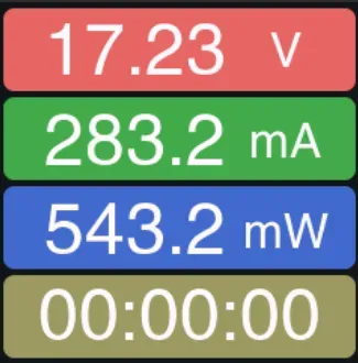
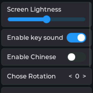
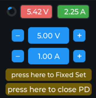
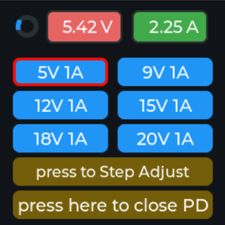
The button operations and various interface displays of Power-Pico are shown below. The top button is the Page Switch/Boot button. Press and hold the top button before powering on to enter Boot mode for a forced firmware upgrade.
The Power-Pico hardware currently supports 2 languages: Simplified Chinese/English.


-
PPS Spoofing Instructions
First, enter the Settings interface, go to the Spoof/Trigger option, click confirm to enter, and then you can adjust the voltage. Note: Currently, only PPS triggering is supported! Make sure to check if your charger block supports the corresponding protocols during testing.

-
Client Operation
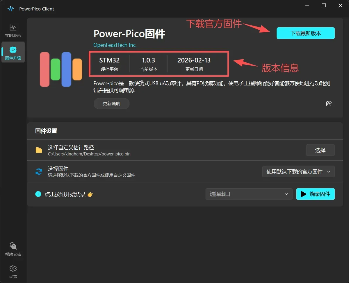
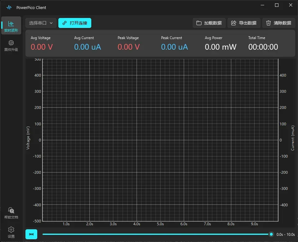
The PowerPico Client for PC can be used for waveform viewing, recording, exporting, and upgrading the firmware of the hardware. The client currently supports 4 languages: Simplified Chinese/Traditional Chinese/English/Japanese.
For detailed instructions on using the PowerPico Client, please refer to: Client Operation Manual



🔍️ Accuracy Measurement
Note: There is usually a resistor (MΩ level) between the VBUS and GND inside a Type-C cable, which will slightly affect the measurement.
Comparison using an SDM3055 6.5-digit multimeter is shown below:


| SDM3055 Reading | Power-Pico Reading | Absolute Error | Relative Error |
|---|---|---|---|
| 52.03 uA | 52.05 uA | 0.02uA | 0.4% |
| 518.84 uA | 518.4 uA | 0.5 uA | 1.0% |
| 5.22 mA | 5.29 mA | 0.07 mA | 1.3% |
| 469.3 mA | 482.7 mA | 13.4 mA | 2.9% |
| 1.78 A | 1.81 A | 0.03 A | 1.7% |
| 5.19 V | 5.24 V | 0.05 V | 1.0% |
| 15.20 V | 15.56 V | 0.36 V | 2.4% |
| 19.98 V | 20.17 V | 0.19 V | 1.0% |
📂 Project Structure
Power-Pico/
├── Firmware/        # Firmware, including BootLoader.hex and App.bin
├── Hardware/        # Schematics
├── 3D models/       # STL files for 3D printing the enclosure
└── Software/        # MDK software project for PowerPico, including BootLoader and App
💻 Code Framework
Similar to previous projects, it uses a BootLoader + App structure for easy USB upgrades. The program partitioning is shown below.
- The initial 48kB area of sectors 0, 1, and 2 is the BootLoader area.
- The 16kB area of the 3rd sector is the upgrade information area, used for verifying the integrity of the App on startup. For specific verification details, see the BootLoader code.
- The area starting from the 4th sector at 0x08010000 is the App area (A/B partitioning is not used due to insufficient on-chip Flash).

High-speed data transmission is performed via USB. The data packet structure is shown below. Each packet contains 100 data sets, totaling 711 bytes including the header.

📖 References
- [1] PD_Micro - USB-C PD3.0 PPS on ATMega32U4 Arduino board
- [2] IoT Power-CC 3D printed shell structure
- [3] PySide6 user manual
- [4] QFluentWidgets - Make QT Great Again
- [5] PyQtGraph user manual
- [6] STM32 USB vitual serial port driver demo
- [7] LVGL - Embedded graphics library
🤝 Contribute
Welcome to submit Issues or Pull Requests to add new features to the project or fix code bugs!!