δΈ­ζ–‡ | English

Power-Pico

A Product-Grade Portable USB Ammeter and Low-Power Measurement Analyzer


--- ## πŸ“– Project Introduction **Power-Pico** is more than just a USB ammeter. It is a **high-precision, low-power analysis tool** designed specifically for embedded developers. To overcome the physical limitations of traditional ammeters in the ΞΌA-level measurement, Power-Pico adopts an innovative **multi-range auto-switching sampling** design, achieving full-range coverage from $1\mu A$ to $5A$.
Display
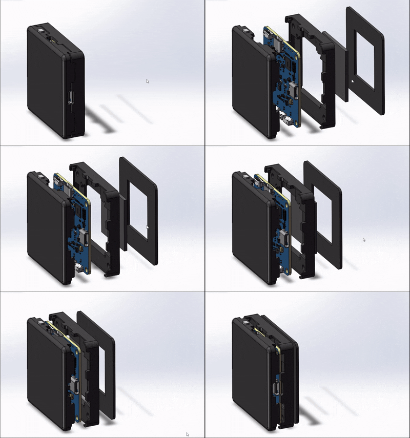
### ✨ Core Features - **ΞΌA-Level High Precision**: Utilizes the INA190 zero-drift amplifier with three-resistor segmented sampling. - **Protocol Trigger**: Supports PD2.0 PPS protocol triggering, with up to 20V/5A output. - **High-Performance UI**: Based on STM32F411 + LVGL v8.3, providing a smooth real-time waveform display. - **Cross-Platform PC Client**: Comes with the Power-Pico Client developed with PySide6, supporting data export and real-time power analysis. - **3D Printed Enclosure**: Provides a complete design for a 3D printed enclosure and acrylic panel. --- ## πŸ› οΈ Hardware Parameter Analysis | Module | Model | Advantage | | :--- | :--- | :--- | | **MCU** | STM32F411CEU6 | 100MHz high frequency, supports DSP instructions to accelerate waveform processing | | **Current Sensing** | INA190 | 0.5nA input bias current, the core guarantee for ΞΌA-level measurement | | **ADC** | 12-bit (STM32 Internal) | Achieves high-speed stable sampling above 10kHz with DMA | | **Screen** | 1.54" TFT (ST7789) | 240x240 resolution, high-contrast display | --- ## πŸš€ Quick Replication ### 1. Hardware Solder the hardware yourself, or purchase a pre-soldered and assembled kit from Taobao. LCSC Open Source Hub page: https://oshwhub.com/no_chicken/powerpico ### 2. Firmware Compilation and Flashing The project is developed based on Keil MDK: 1. Clone the repository: `git clone https://github.com/kingham/Power-Pico.git` 2. Flash the BootLoader via the SWD port. 3. Compile PowerPico yourself. The generated `.bin` file can then be flashed using the PowerPico Client. ### 3. Assembly The physical assembly is shown in the figure below: The exploded 3D view is as follows:
3D Exploded View Left
3D Exploded View Right
### 4. Running the PC Client Install and use the PowerPico Client. Currently, it only supports Windows. ## πŸ› οΈ User Guide 1. Hardware Operation The button operations and various interface displays of Power-Pico are shown below. The top button is the **Page Switch/Boot** button. Press and hold the top button before powering on to enter Boot mode for a forced firmware upgrade. The Power-Pico hardware currently supports 2 languages: **Simplified Chinese/English**.
Button Functions
Startup Page
Main Page
Settings Page
PPS Page 1
PPS Page 2
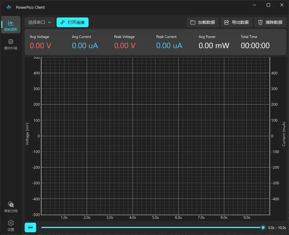
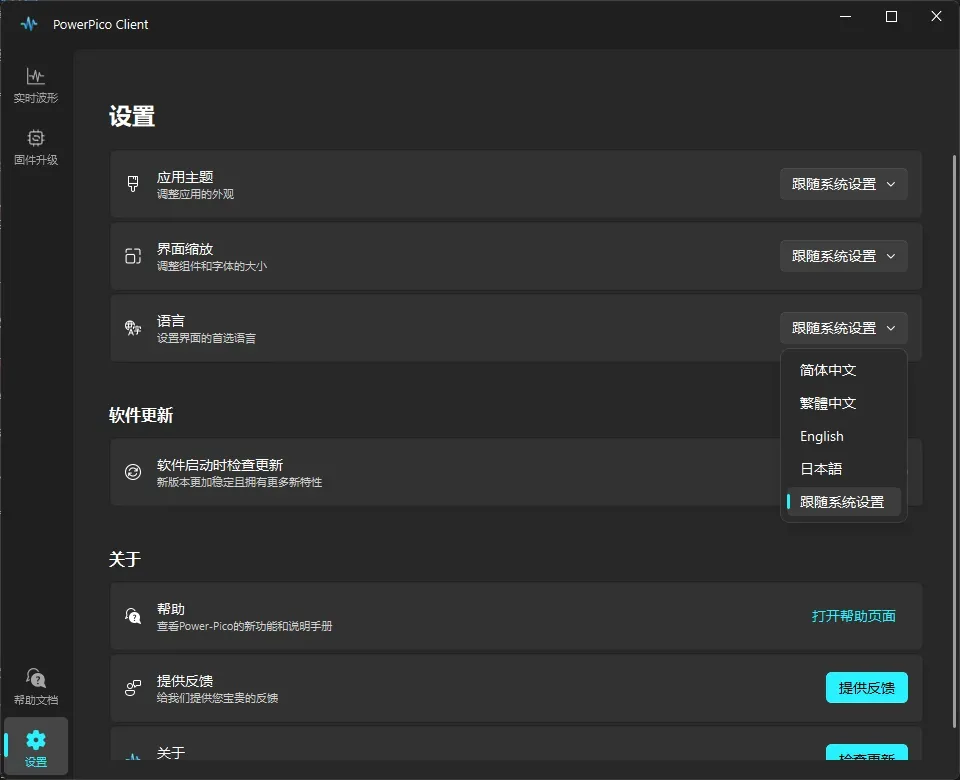
2. Client Operation The PowerPico Client for PC can be used for waveform viewing, recording, exporting, and upgrading the firmware of the hardware. The client currently supports 4 languages: **Simplified Chinese/Traditional Chinese/English/Japanese**. For detailed instructions on using the PowerPico Client, please refer to: [Client Operation Manual](https://no-chicken.com/content/Power-Pico/UserManual/client_operation.html)
Waveform Interface
Firmware Upgrade Interface
Waveform Interface 2
Settings Interface
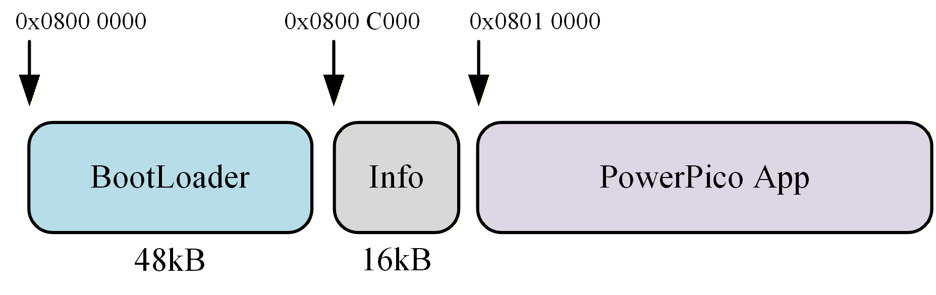
## πŸ“‚ Project Structure ```text Power-Pico/ β”œβ”€β”€ Firmware/ # Firmware, including BootLoader.hex and App.bin β”œβ”€β”€ Hardware/ # Schematics β”œβ”€β”€ 3D models/ # STL files for 3D printing the enclosure └── Software/ # MDK software project for PowerPico, including BootLoader and App ``` ## πŸ’» Code Framework Similar to previous projects, it uses a BootLoader + App structure for easy USB upgrades. The program partitioning is shown below.
Flash Partitioning
High-speed data transmission is performed via USB. The data packet structure is shown below. Each packet contains 100 data sets, totaling 711 bytes including the header.
Data Packet Structure
πŸ“– References 🀝 Contribute Welcome to submit Issues or Pull Requests to add new features to the project or fix code bugs!!